AppliedAppplications™ Real Solutions for Real Applications
What do the IpTL Gateway Appliances Do?
The World’s Longest Ethernet Cable™
Connecting your devices over a network has always been challenging. Routers, Network Addressing, and WAN links make even the simplest of connections difficult and expensive. Most VPN’s focus on security rather than connectivity. This means establishing a site-2-site link requires expensive infrastructure and difficult configurations.
A VPN or Tunnel on its own lacks the tools needed for integration, simplicity, and reliability. And most VPNs are not compatible with SCADA/PLCs, which require a unified network addressing and LAN-based networking. But IpTL has created and integrated technologies to ensure an easy, seamless, stable, and secure link.
We can connect remote Ethernet SCADA, PLC, and HMI devices from remote sites back to your headend. Whether you have a network infrastructure, Internet, or partial connectivity, we can connect, secure, and unify your devices.
Key points about IpTL for Connecting SCADA, PLC, Display/HMI Controllers
- Seamless End-to-End connectivity for SCADA & PLC devices over any IP network – including dynamic and private IP’s
- Dynamic IP ok! No need for a static IP.
- Plug-and-Play No-Configure Point-to-Point links with our AutoConnect™
- VLAN’s over the Internet with Ethernet level networking
- Reliably connect through firewalls/NATs
- Full end-to-end Encryption with AES256
- Fully out-of-band manageable
- Works with any Ethernet-based device
- Full Security to lock-down and lock-out unauth access
How to Connect a Single Remote Site
Point-to-Point
Connecting One or more SCADA Devices From a Single Site
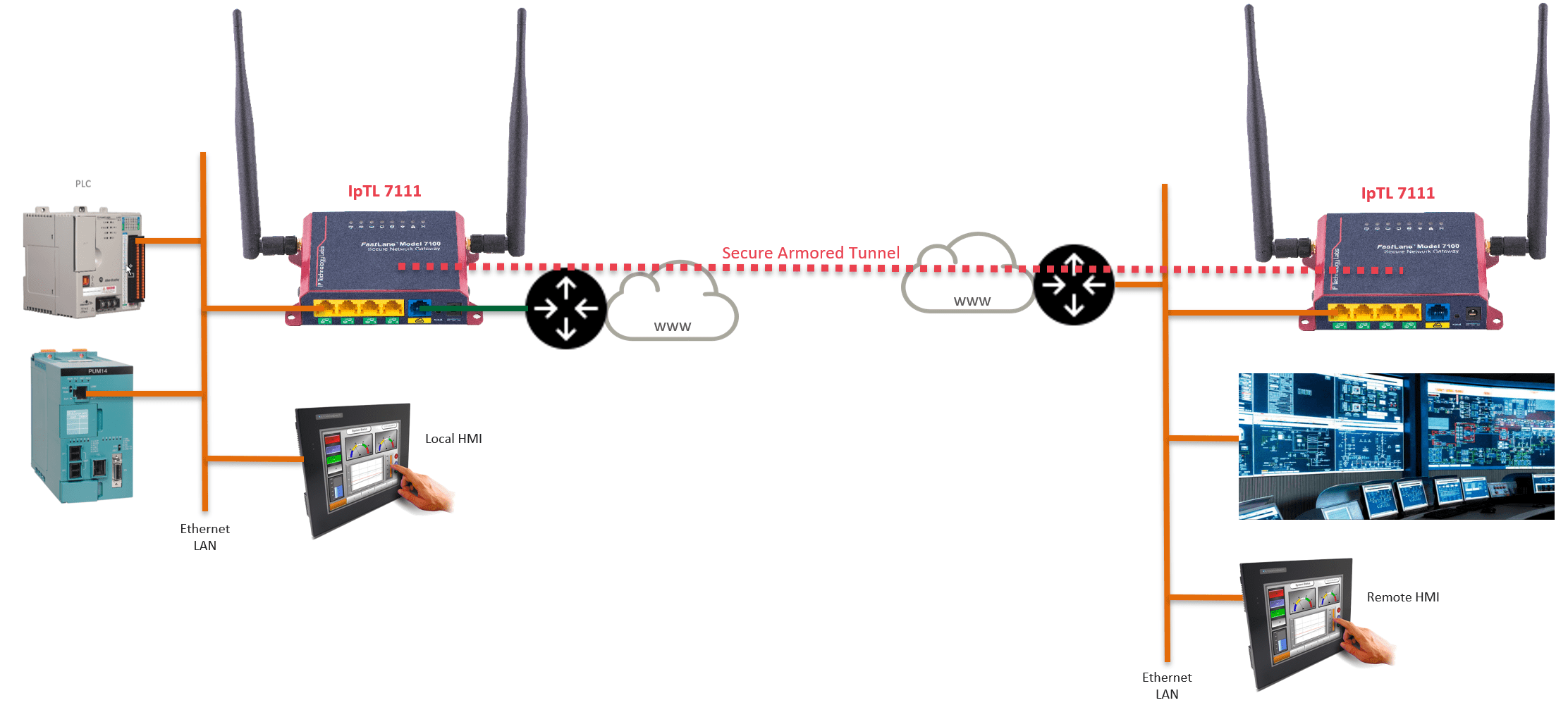
Connecting a one or more industrial devices back to your headend can be easy. With the IpTL exclusive AutoConnect™ feature it can be as straightforward as plugging in the appliances, plugging in your devices, and powering up.
As “The World’s Longest Ethernet Cable”, AutoConnect™ enables a secure plug-and-play Layer 2 LAN Extension without any configuration. Even behind routers & NATs or on Dynamic IP links. This enables you to take the headend LAN and seamlessly extend to your remote devices.
It is just like extending a cable from your Ethernet switch to your remote site. And because it is L2/Ethernet-based, it enables devices that only work on the same LAN to operate without issue.
With AutoConnect™, it is as easy as plugging in your Ethernet and powering up!
Click here to see more about AutoConnect™.
How Does it Work
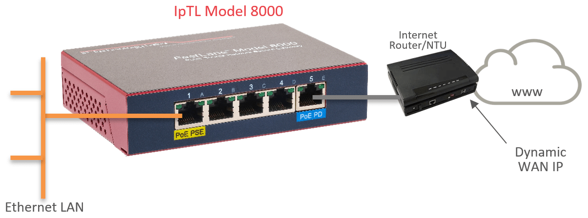
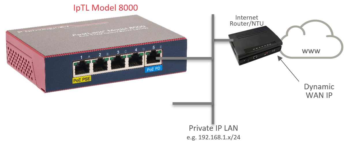
For the remote IpTL appliance, connect the uplink port (blue) to the LAN switch or directly to the Internet router. The IpTL appliance can be installed behind an existing NAT, Firewall, or router with a DHCP private address. No port forward or configuration is required.
The uplink port will DHCP and begin to create a link. If using AutoConnect™ the appliances will work to establish a direct connection through your existing router/NAT.
The SCADA controllers are connected to one of the local ports (yellow) on the IpTL appliance. These yellow local ports will be transparently connected to the headend LAN once the tunnel is established…of course all the communications will be encrypted with AES256 end-to-end.
On the HeadEnd or central site, all that is required is a single Ethernet on the local port.
Because you are extending the headend LAN all the networking will be the same for the remote site. If your PLC can DHCP for an address the response will come from your headend LAN and operate just like it is sitting on your headend network.
All IpTL appliances are full routers so if separate routed networks or translations are required we can integrate your remote devices and networks without issue.
You can access the PLC or display controller just like you would if it was installed on the local LAN.
How to Devices at Multiple Sites
Point-to-MultiPoint
Connecting Multiple Sites
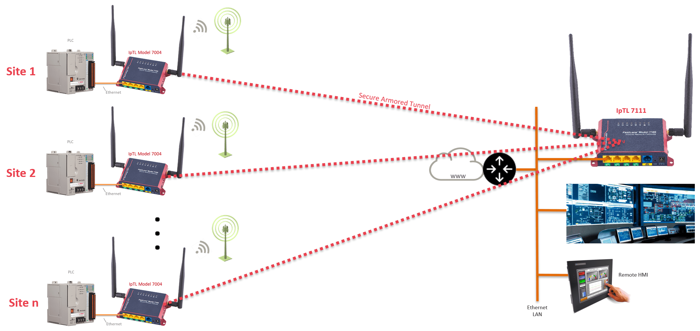
Connecting multiple remote sites is straightforward. To establish a tunnel, each remote appliance is simply configured with the IP, FQDN name, or the MAC address of the headend appliance.
When a remote appliance is powered on it will continuously attempt to connect to the headend. The remotes do not require any port forward rules and can be installed behind a router, NAT, or firewall.
The headend appliance will terminate all the remotes appliances.
The headend can support either Bridged/L2 or Routed/L3 connections. If bridged, the LAN will be extended to all sites, and the networking is shared. If routed, then each site will have its own IP network range.
Using the client-to-client setting on the headend appliance, all remote sites can be either blocked from direct communication, called hair-pinning, or allowed to communicate directly with each other.
To enhance security, the Tunnel Auth feature can be set with a user passphrase. Once set, all the appliances will be in a closed user group preventing outside connections from any device.
How Does it Work
To make a tunnel, each remote will be configured with the IP, Name, or simply the MAC address of the headend appliance under the Tunnel Options page.
Here is an example entry on a remote appliance: ![]()
IpTL’s appliances enable you to use Dynamic IP Internet services at both the remote and the headend. IpTL’s patented RealTimeResource™ feature automatically resolves the current headend IP address with DNS.
If the tunnel is Ethernet/L2 then the Local Port at the remote and the headend will be connected. If the tunnel is Routed/L3, then the headend appliance will automatically push all the routes to each remote appliance.
If Routed/L3 operation is used and the remote appliance is in a stub installation then it may be necessary to configure the remote router to send traffic to the IpTL appliance as the next hop for its networks.
Connect With Self-Deployed Network
Point-to-Point
Point-to-MultiPoint
Connecting With No Established Infrastructure
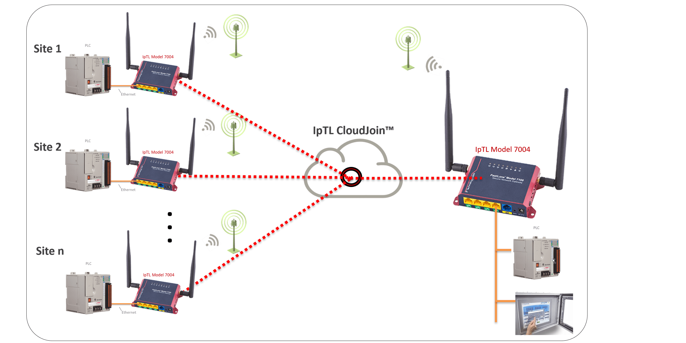
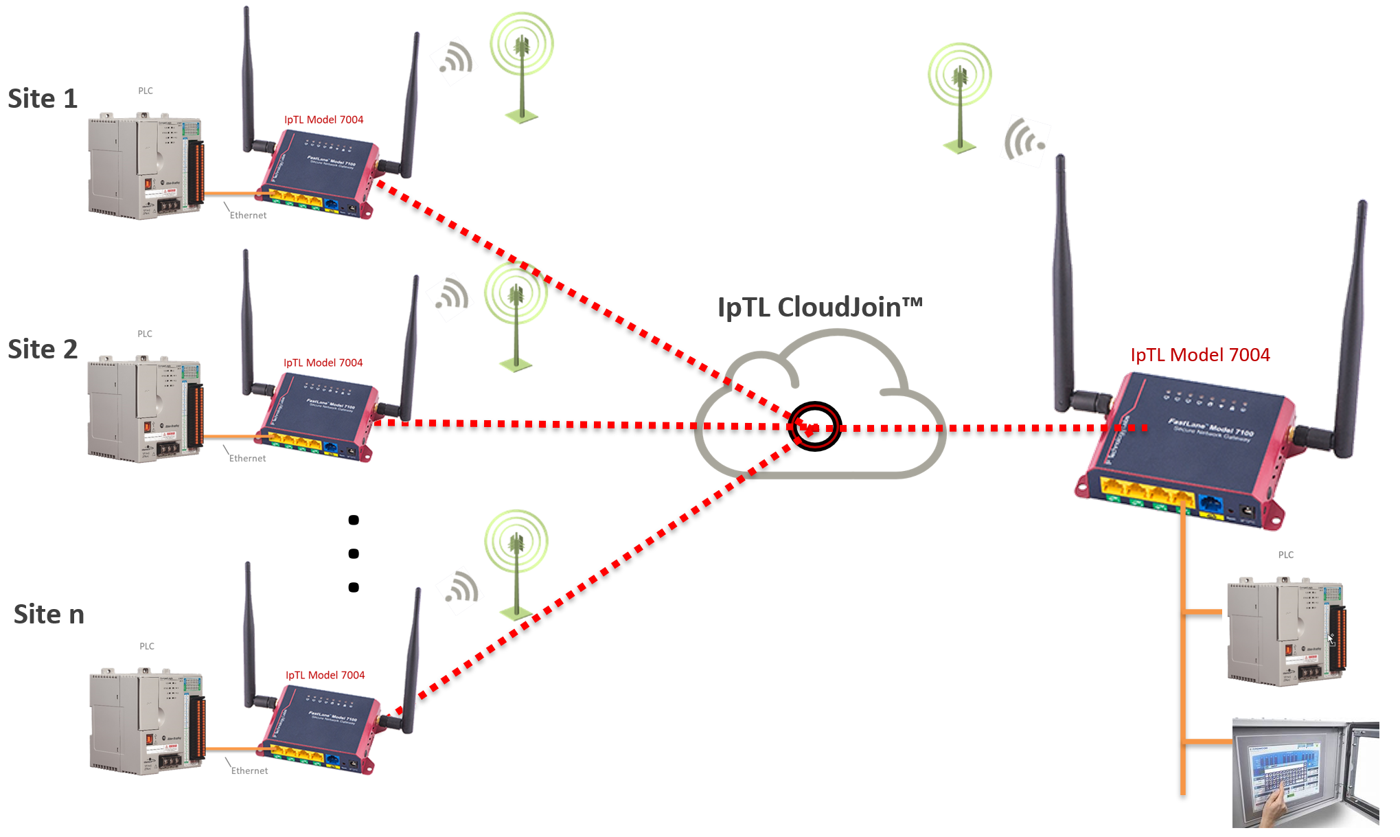
Connecting one or more remote sites when there is no existing network is easy. Using IpTL’s CloudJoin™ remote and headend devices can be connected with a “Network-in-the-Cloud” virtual switching service. Using redundant network servers in Tier-1 data centers, CloudJoin™ ensures easy and secure connectivity over any Internet.
Each CloudJoin™ is dedicated per customer network. Two or more IpTL appliances will connect, with unique security parameters. Once the appliances are connected data will move freely between them. CloudJoin™ supports any network addressing, including VLANs, broadcast, and multicast. Plus, you can add additional remotes at any time.
The headend can support either Bridged/L2 or Routed/L3 connections. If bridged, the LAN will be extended to all sites, and the networking is shared. If routed, then each site will have its own IP network range.
Using the client-to-client setting on the headend appliance, all remote sites can be either blocked from direct communication, called hair-pinning, or allowed to communicate directly with each other.
To enhance security, the Tunnel Auth feature can be set with a user passphrase. Once set, all the appliances will be in a closed user group preventing outside connections from any device.
How Does it Work
To make a tunnel, each remote will be configured with the IP, Name, or simply the MAC address of the headend appliance under the Tunnel Options page.
Here is an example entry on a remote appliance: ![]()
IpTL’s appliances enable you to use Dynamic IP Internet services at both the remote and the headend. IpTL’s patented RealTimeResource™ feature automatically resolves the current headend IP address with DNS.
If the tunnel is Ethernet/L2 then the Local Port at the remote and the headend will be connected. If the tunnel is Routed/L3, then the headend appliance will automatically push all the routes to each remote appliance.
If Routed/L3 operation is used and the remote appliance is in a stub installation then it may be necessary to configure the remote router to send traffic to the IpTL appliance as the next hop for its networks.
How to Connect using Internet
How to Connect Using Generic Internet
Remote Site Behind a NAT/Firewall
In-line with Router
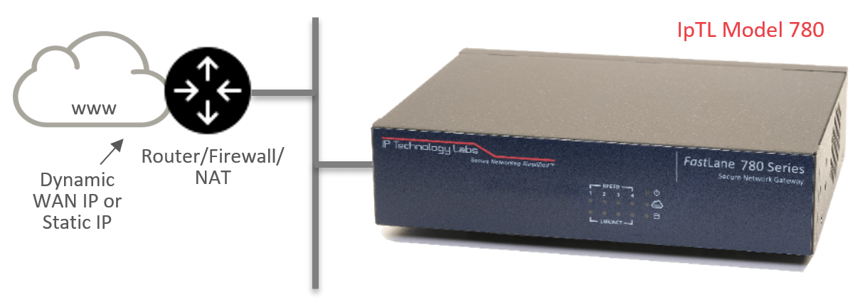
IpTL appliances can be installed behind a NAT router or firewall as well as on Dynamic IP links. One installation option is In-Line where the IpTL appliance is used as the router for the remote network.
The appliance supports DHCP server, DNS, VLAN, Virtual Routers, ACL firewall as well as full next-hop route control. Any tunnel created will be able to connect to the local LAN for secure access back to the headend. Connections can be set for Split-Tunnel or Compulsory-Tunnel to ensure the remote data goes where you want it.
In-line can be Bridged/L2 for smaller sites or Routed/L3 for larger scalable installations.
Remote Site Behind a NAT/Firewall
Stub
IpTL appliances can be installed as a stub host on the network. This type of installation is often used when it is desired to isolate devices from the local LAN while connected to the headed via a remote access tunnel.
This type of operation can be used with Ethernet/L2 or Routed/L3 connections. If there is a desire for hosts on the local LAN to communicate to the headend through a tunnel then it may be required to configure a next-hop routing rule in the default router.
Alternatively, IpTL’s patent-pending IPShare™ can be used to create a local LAN interface on the tunnel.
HeadEnd Behind a NAT/Firewall
An appliance can be installed as a server behind a NAT router as well as on a Dynamic IP link. The headend appliance listens for incoming tunnel connections and will authenticate valid remote sites.
When installed behind a NAT, it will be necessary to configure the upstream router with a single port-forward statement to send inbound traffic to the IpTL appliance. All remote connections will use this port forward.
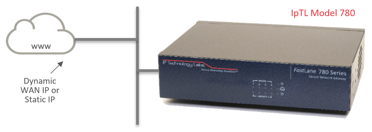
HeadEnd Directly Connected to the Internet
An appliance configured as a server can also be directly attached to the Internet with either a static or dynamic IP. In such cases, there is no requirement for a port-forward rule as all incoming connections will be direct to the appliance.
As every IpTL appliance is a router/NAT/firewall, all non-tunnel external connections can be blocked, and only legitimate IpTL remote appliances can connect.
How to Connect using Cellular
How to Connect Using Cellular LTE
Cellular/LTE Modem for Remote Internet
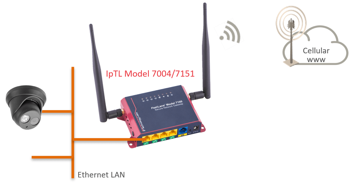
Many times a remote site will not have Internet service available. For those remotes, IpTL offers the Model 7004VZ (Verizon Certifed) and the Model 7151 (International/Global) appliances with built-in Cellular/LTE modems.
The modem takes a standard SIM card for data service and will receive a private and dynamic address from the carrier network. Once powered up and attached to the Cellular network, the IpTL remote appliance will continuously and automatically connect to the headend just like it was on a wired Internet.
Once the tunnel is established, direct communications are available to the remote network. This supports both Ethernet/L2 and Route/L3 type network architecture.
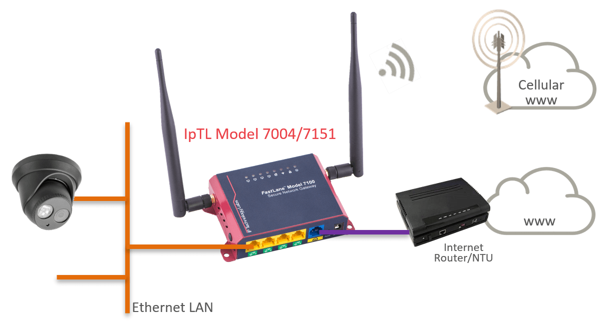
Cellular/LTE as On-Demand Failover/Redundancy
When a link up-time is critical, the IpTL Cellular/LTE appliance can be used as an on-demand failover to the local Internet access. Using our SystemMonitor™ feature, it is possible to have fast and responsive link protection.
SystemMonitor™ supports:
- Supports Active/Active, Active/Standby, and Active/Hot-Standby failure ready operation
- Highly Configurable Down-Time monitors, with configurable hysteresis that goes way beyond a simple PING
- Triggered networking actions to ensure your network runs the same in any failure
See the Magic for Yourself with our Free Trial Demo
Sometimes you just need to see it for yourself. We’ve setup a program to do just that. Click the Try Now if you want to see the magic of IpTL absolutely reliable networking!