AppliedAppplications™ Real Solutions for Real Applications
How to Connect Without Router, NAT, Firewall, or Network Changes
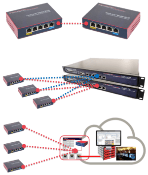
Connect Without Remote Router or Network Changes
Connect on Networks you Don’t Control
Often there are remote IP network cameras on previously installed or established networks. Changing these production networks can be troublesome. It will require either extensive IT manpower and troubleshooting, or it is administratively locked down from any modification.
Often these remote networks will have overlapping addresses with other sites making an IPsec VPN unusable.
IpTL’s patent-pending IPShare™ integrates an Ethernet tunnel interface, a routed LAN connection, and a source connection translation engine to enable communications without changes.
Now, it is possible to install an IpTL appliance on a remote network without having to worry about the following:
- Default router next-hop configurations
- Overlapping Network spaces
- Unified HeadEnd access without having to know endpoint addresses
Additionally, the upstream network is protected from random remote devices from “swimming upstream” in the headend network.
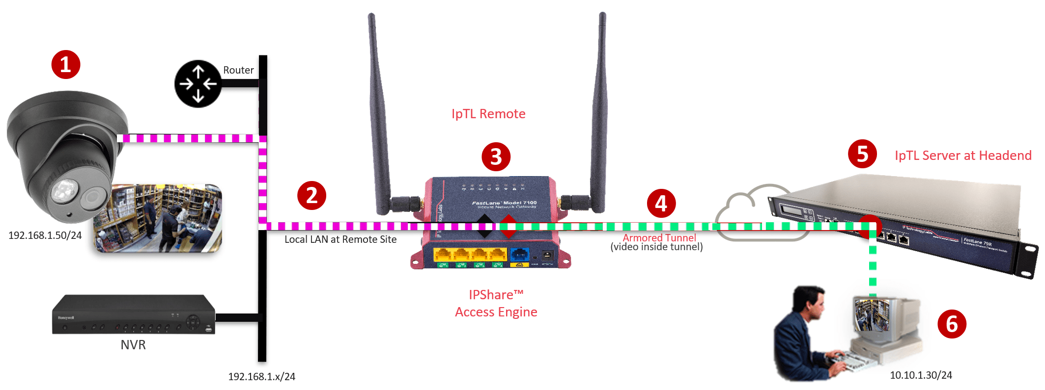
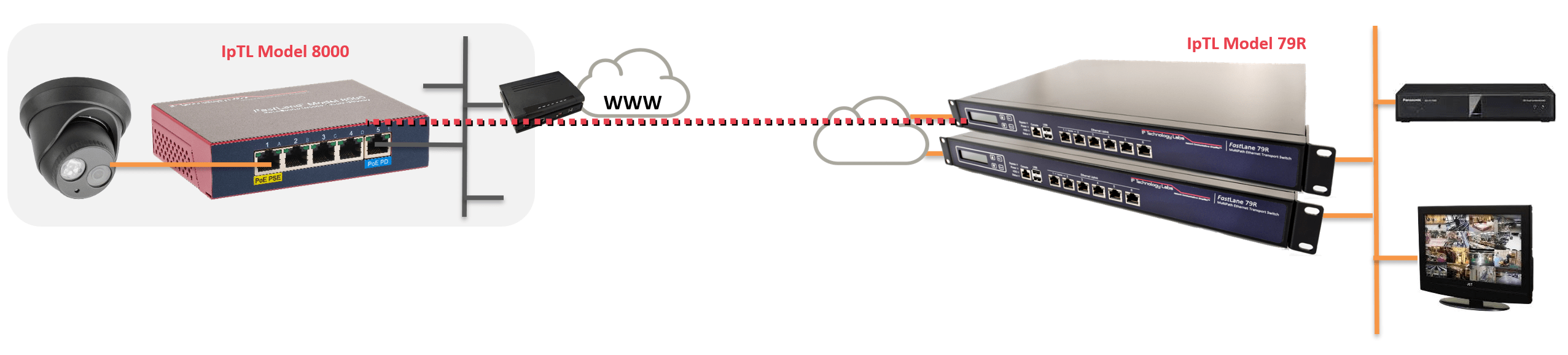
How Does it Work
The system creates a bridged tunnel from the server to the appliance. The Tunnel interface has an IP address on the Server/Headend network. Then a routed NAT connection is created between the remote appliance’s Ethernet LAN interface and the Tunnel interface.
Rules are then put into to enable the server network (NAT) translated to the IP Cams, NVR, or devices on the LAN. Because the IpTL appliance (3) provides dynamic source NAT to the server network requests, all the network hosts on the LAN know how to send the data back automatically.
No Router configuration is required for the “next-hop” router as well as no changes to the installed network are needed.
This allows unlimted access to remote cameras even if each remote network is an overlapping or has conflicting network addresses. Security is enhanced as the remote LAN traffic does not travel upstream towards the headend unless it has been requested by the headend first.
Additional security can be added with IpTL’s patented SuperNAC™ feature to ensure only the correct and authorized device can communicate.
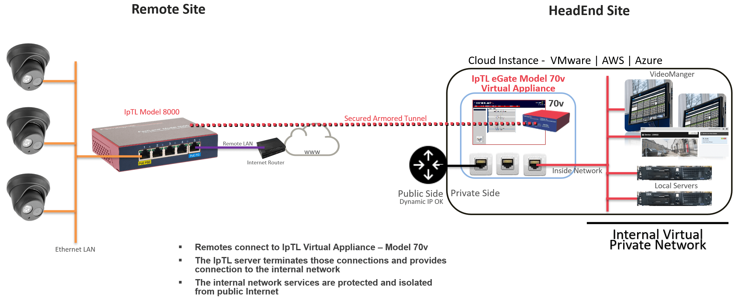
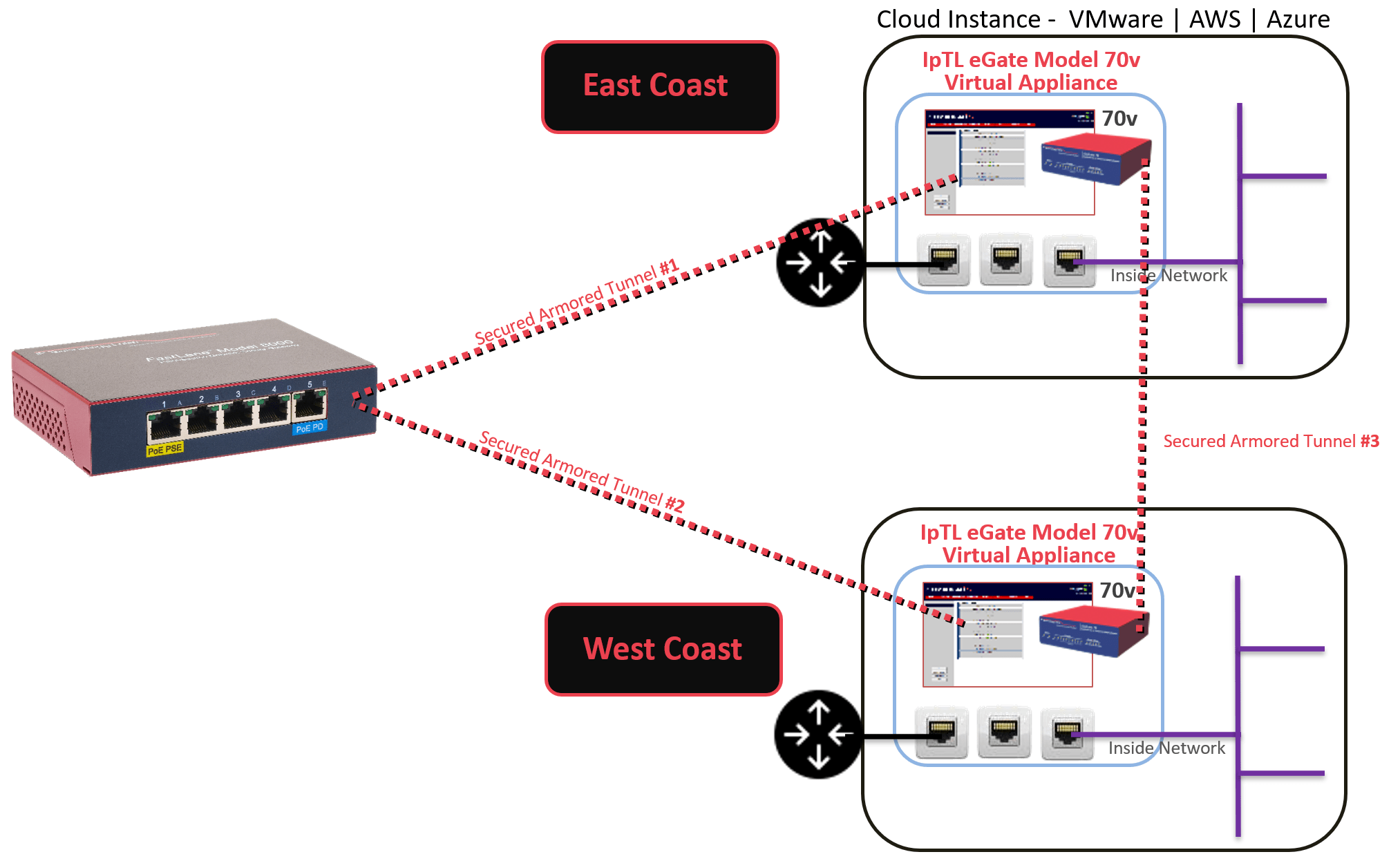
Physical-to-Cloud
Connecting Remote Physical Devices to Cloud or Virtual Servers
Many central compute resources are now moving to virtual deployments such as VMware or public clouds like AWS and Azure. IpTL VPN/Tunnel servers can easily be deployed in your private or public cloud and provide the physical-device-to-application connectivity.
The IpTL Model 70v server operates just like a physical appliance and provides the same connectivity and security options as a hardware appliance. Typical deployments would have a virtual Ethernet connection to the Internet/WAN and one or more virtual Ethernet ports connected to the internal Virtual Private Cloud network.
Once a remote IpTL appliance is connected to the server and is authenticated, then the remote network is available to the internal applications.
Larger installations can “stack” additional Model 70v appliances in the same VM or in separate VM’s and still link for seamless access.
Security is enhanced for your applications as cloud access can only occur with a valid IpTL link. Denial-of-Service attacks are limited as invalid data on tunnel ports is immediately dropped.
How Does it Work
To make a tunnel, each remote will be configured with the IP, Name, or simply the MAC address of the headend appliance under the Tunnel Options page.
Here is an example entry on a remote appliance: ![]()
IpTL’s appliances enable you to use Dynamic IP Internet services at both the remote and the headend. IpTL’s patented RealTimeResource™ feature automatically resolves the current headend IP address with DNS.
If Routed/L3 operation is used and the remote appliance is in a stub installation, then it may be necessary to configure the remote router to send traffic to the IpTL appliance as the next hop for its networks.
The installation footprint of the Model 70v Virtual is extremely small. Most initial installations only require a 2Ghs dual-core, 60 MB of storage, and 1 GB of RAM. Of course, you scale up to 1,000+ connections by simply adding more compute resources at any time.
Redundancy, Resiliency & Failover
Always Up Failover/Restore Protection
WAN link Protection N+1 or N+N
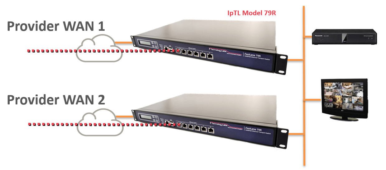
Multi ISP Provider Failover
Providing redundant connections with multiple ISPs is a cost-effective way to achieve high reliability.
Supporting up to 64 different physical paths and adding redundancy is as easy as plugging in another provider to the appliance.
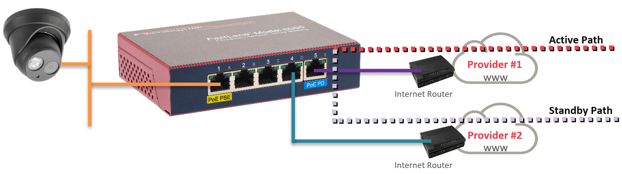
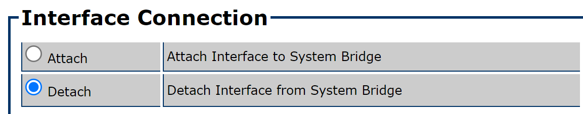
To add another Internet path, simply “detach” the Ethernet port you wish to use and connect the secondary ISP router.
The primary path will carry the tunnel/data with the secondary’s ready if the primary fails.
To automate the failover/restore, IpTL’s patent-pending SystemMonitor™ enables fast, automatic, & deterministic path switching.
Going beyond a standard “ping,” SystemMonitor™ can ensure end-to-end connectivity and provide the fastest failover switching available.
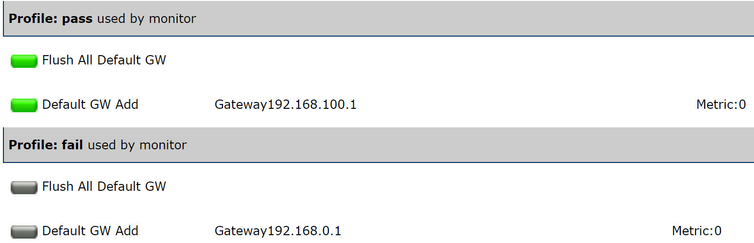
IpTL’s SystemMonitor™ is set up to actively monitor connectivity to the headend site over the primary ISP path.
If connectivity to that end-point becomes unavailable, then the system will switch to the backup link. Once the primary is reestablished, the appliance will automatically switch back to the primary.
IpTL’s SystemMonitor™ is extremely flexible and tunable to enable you to have your appliance work exactly as you want.
Tunnel/VPN Resiliency
We keep your tunnel Unblocked, Unfiltered, & Private
You expect your links are private, and it shouldn’t be obvious what your communications are. Traffic analysis and inference attacks can deduce information from your patterns and can be performed even when the traffic is encrypted.
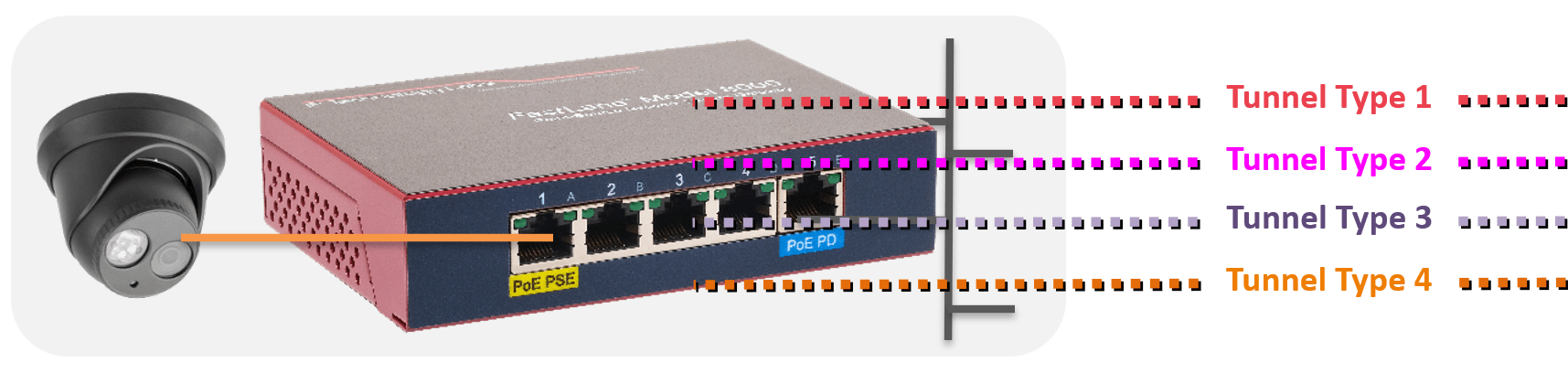
IpTL’s BlackNoise™ set of obfuscation and path optimization techniques can remove tunnel, data, & traffic fingerprints and keep your links unblocked, secured, and private.
It is trivial to filter our IPsec tunnels, and many firewalls and proxies are doing just this. Simply, IPsec cannot give you privacy, security, or the ability to remain unblocked.
![]()
WAN link Protection Cellular/LTE Failover
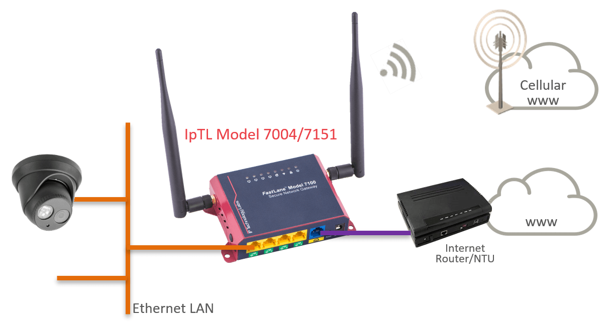
A common redundancy option is using our appliance, such as the Model 7151 or 7004, with a built-in Cellular/LTE modem along with our SystemMonitor™ feature.
Here the Cellular modem is disconnected until the primary path is unavailable. During this time, no data is used across the cellular connection lowering overall costs.
When a fault condition is detected, the Cellular modem is connected to Cellular data, and the tunnel is reestablished over that path.
Once the primary path is available and stable, the modem is disconnected, and the tunnel is now over the primary path connection.
The appliance can use dynamic IP and private/NAT IP services from the carrier to ensure the use of the lowest-cost, most standard cellular data services.
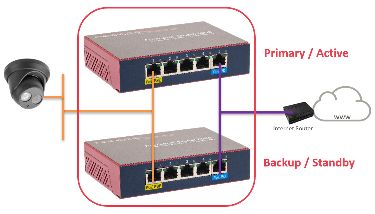
Device Failure Protection N+1 or N+N
When protecting against physical device failures, IpTL appliances can be “stacked” into a cluster. Running VRRP allows a primary appliance to operate with one or more appliances in standby mode. If the primary appliance fails, the secondary appliance steps in. This is all transparent to the WAN and LAN operation. In all cases, there is one appliance operating as the primary.
Typical installations use 1+1 redundancy where one appliance is a backup to another. It is possible to stack-up multiple appliances to achieve a N+1 where you have many appliances protecting the primary.
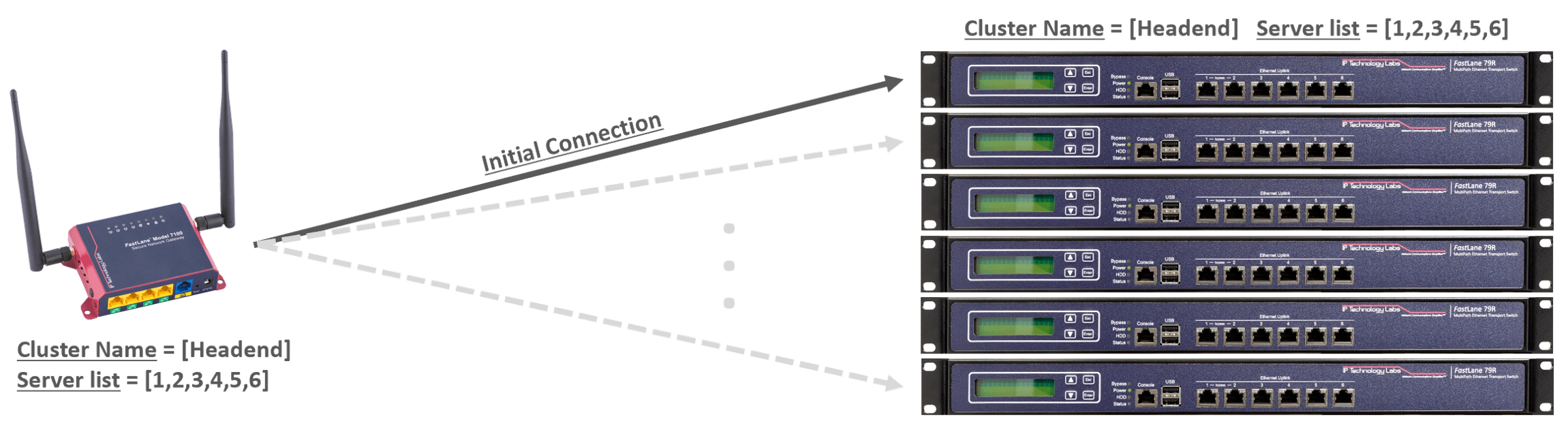
Headend Redundancy N+1 or N+N
Headend or central site redundancy is popular when there are more than 10 simultaneous remotes to a server. At the central site, redundancy can be as easy as stacking multiple servers, each with its own Internet WAN link.
Installations can use multiple servers which take connections from all remotes or clustered using VRRP. For larger installs, multiple IpTL servers can be clustered into a resource group. Using our patent-pending OnNet™ controllerless high-availability features, central site resources are available to all remote appliances without enduring a bottleneck from an intermediate controller system.
Each LAN port on the IpTL server can connect to the same LAN switch or for true redundancy, separate switches. To further enhance uptime, each IpTL appliance should be connected to different power buses.
In any case, IpTL appliances can be deployed to eliminate any single point of failure across device-path-power-switching resources.
Headend Redundancy with Physical Resiliency
IpTL makes it easy to harden your network while providing seamless connectivity. It may be desirable to have a remote appliance simultaneously connect to multiple physical servers which may be physically separated.
Following a meshed-type connection, strategy enables resiliency from the data center or significant network outages. In this case, resources can be directly accessed through one or more data center paths without relying on a single point-to-point link for operation.
This type of deployment is also useful for main site and disaster recovery site connectivity where day-to-day IT operation traffic is communicating to the headend but also backups are done directly to the DR site.
See the Magic for Yourself with our Free Trial Demo
Sometimes you just need to see it for yourself. We’ve setup a program to do just that. Click the Try Now if you want to see the magic of IpTL absolutely reliable networking!